

How To Set Default Gateway On Cisco Switch
Basic Switch Configuration (two.1)
Switches are one of the nearly numerous devices installed onto the corporate network infrastructure. Configuring them tin exist fun and challenging. Knowing how switches normally boot and load an operating system is besides important.
Switch Boot Sequence (2.ane.i.i)
Subsequently a Cisco switch is powered on, it goes through the following boot sequence:

Step 1. Outset, the switch loads a power-on self-test (POST) plan stored in ROM. POST checks the CPU subsystem. It tests the CPU, DRAM, and the portion of the flash device that makes up the flash file system.
Step 2. Next, the switch loads the boot loader software. The kick loader is a small-scale program stored in ROM and is run immediately after Mail successfully completes.
Step iii. The boot loader performs low-level CPU initialization. It initializes the CPU registers that control where concrete retentivity is mapped, the quantity of memory, and memory speed.
Footstep four. The boot loader initializes the flash file system on the system board.
Step 5. Finally, the boot loader locates and loads a default IOS operating organization software image into retention and hands command of the switch over to the IOS.
The kicking loader finds the Cisco IOS image on the switch using the following process: The switch attempts to automatically kick by using information in the Kicking environment variable. If this variable is non set, the switch attempts to load and execute the first executable file it can by performing a recursive, depth-first search throughout the flash file system. In a depth-first search of a directory, each encountered subdirectory is completely searched before standing the search in the original directory. On Catalyst 2960 Series switches, the image file is usually contained in a directory that has the same proper noun equally the image file (excluding the .bin file extension).
The IOS operating system then initializes the interfaces using the Cisco IOS commands found in the configuration file, startup configuration, which is stored in NVRAM.
In Figure 2-1, the Kicking environs variable is set using the kick system global configuration fashion command. Utilise the show bootvar command (show boot in older IOS versions) to see the current IOS boot file version.
Recovering from a System Crash (two.1.i.2)
The boot loader provides access into the switch if the operating system cannot be used considering of missing or damaged system files. The boot loader has a command line that provides access to files stored in flash memory.
The boot loader can be accessed through a panel connection using these steps:
Step ane. Connect a console cable from the PC to the switch panel port. Configure terminal emulation software to connect to the switch.
Stride 2. Unplug the switch power cord.
Step 3. Reconnect the ability string to the switch and within xv seconds printing and hold downwards the Mode button while the System LED is still flashing green.
Stride four. Continue pressing the Manner button until the System LED turns briefly bister and and then solid green; then release the Fashion button.
Step 5. The boot loader switch: prompt appears in the terminal emulation software on the PC.
The kick loader command line supports commands to format the flash file organisation, reinstall the operating arrangement software, and recover from a lost or forgotten password. For example, the dir command can exist used to view a list of files within a specified directory as shown in Figure 2-2.
Switch LED Indicators (2.i.1.3)
Cisco Goad switches have several condition LED indicator lights. You can employ the switch LEDs to quickly monitor switch activity and its performance. Switches of different models and feature sets will have different LEDs, and their placement on the front panel of the switch may as well vary.
Effigy 2-3 shows the switch LEDs and the Fashion button for a Cisco Catalyst 2960 switch. The Mode button is used to toggle through port condition, port duplex, port speed, and PoE (if supported) condition of the port LEDs.
Table two-i contains the purpose of the Cisco 2960 switch LED indicators, and the meaning of their colors.
Table 2-1 Purpose of Cisco Switch LEDs
| Organisation LED | Shows whether the organisation is receiving ability and is functioning properly. If the LED is off, it means the organization is not powered. If the LED is green, the system is operating commonly. If the LED is amber, the organization is receiving power but is not functioning properly. |
| Redundant Power System (RPS) LED | Shows the RPS condition. If the LED is off, the RPS is off or not properly connected. If the LED is dark-green, the RPS is continued and ready to provide fill-in power. If the LED is blinking dark-green, the RPS is continued but is unavailable because it is providing power to some other device. If the LED is amber, the RPS is in standby style or in a fault condition. If the LED is blinking amber, the internal power supply in the switch has failed, and the RPS is providing ability. |
| Port Status LED | Indicates that the port condition mode is selected when the LED is light-green.This is the default fashion. When selected, the port LEDs volition display colors with unlike meanings. If the LED is off, there is no link, or the port was administratively shut down. If the LED is green, a link is present. If the LED is blinking green, there is activity and the port is sending or receiving data. If the LED is alternate green-amber, there is a link fault. If the LED is amber, the port is blocked to ensure a loop does not exist in the forwarding domain and is not forwarding data (typically, ports will remain in this country for the first 30 seconds subsequently being activated). If the LED is blinking bister, the port is blocked to prevent a possible loop in the forwarding domain. |
| Port Duplex LED | Indicates the port duplex mode is selected when the LED is green. When selected, port LEDs that are off are in one-half-duplex mode. If the port LED is light-green, the port is in full-duplex mode. |
| Port Speed LED | Indicates the port speed fashion is selected. When selected, the port LEDs will display colors with unlike meanings. If the LED is off, the port is operating at x Mb/s. If the LED is dark-green, the port is operating at 100 Mb/s. If the LED is blinking green, the port is operating at 1000 Mb/s. |
| Ability over Ethernet (PoE) Mode LED | If PoE is supported, a PoE mode LED will be present. If the LED is off, it indicates the PoE style is not selected and none of the ports take been denied power or placed in a fault status. If the LED is blinking amber, the PoE way is not selected only at to the lowest degree one of the ports has been denied power, or has a PoE fault. If the LED is green, it indicates the PoE mode is selected and the port LEDs will display colors with different meanings. If the port LED is off, PoE is off. If the port LED is light-green, PoE is existence provided to a device. If the port LED is alternating green-bister, PoE is denied considering providing power to the powered device will exceed the switch power chapters. If the LED is blinking amber, PoE is off due to a mistake. If the LED is bister, PoE for the port has been disabled . |
Preparing for Basic Switch Management (2.one.i.4)
To prepare a switch for remote direction access, the switch must be configured with an IP address and a subnet mask. Keep in mind that to manage the switch from a remote network, the switch must be configured with a default gateway. This is very similar to configuring the IP address information on host devices. In Figure 2-iv, the switch virtual interface (SVI) on S1 should be assigned an IP accost. The SVI is a virtual interface, non a concrete port on the switch.
SVI is a concept related to VLANs. VLANs are numbered logical groups to which concrete ports can be assigned. Configurations and settings applied to a VLAN are also applied to all the ports assigned to that VLAN.
By default, the switch is configured to have the management of the switch controlled through VLAN 1. All ports are assigned to VLAN 1 by default. For security purposes, it is considered a best practice to utilise a VLAN other than VLAN 1 for the management VLAN. Furthermore, it is also a best practice to employ a VLAN that is non used by end devices such as users and printers.
Configuring Basic Switch Management Access with IPv4 (two.one.i.5)
Step 1. Configure the Management Interface.
-
An IP accost and subnet mask is configured on the management SVI of the switch from VLAN interface configuration way. As shown in Table 2-2, the interface vlan 99 command is used to enter interface configuration fashion. The ip address command is used to configure the IP address. The no shutdown command enables the interface.
Tabular array 2-2 Configure the Switch Management Interface
| Enter global configuration mode. | S1# configure concluding |
| Enter interface configuration mode for the SVI. | S1(config)# interface vlan 99 |
| Configure the management interface IP address. | S1(config-if)# ip address 172.17.99.eleven 255.255.0.0 |
| Enable the direction interface. | S1(config-if)# no shutdown |
| Return to privileged EXEC mode. | S1(config-if)# end |
| Save the running config to the startupconfig. | S1# re-create running-config startup-config |
-
In this example, VLAN 99 is configured with the IP address and mask of 172.17.99.xi. To create a VLAN with the vlan_id of 99 and associate it to an interface, use the following commands:
S1(config)# vlan vlan_id S1(config-vlan)# name vlan_name S1(config)# end S1(config)# config terminal S1(config)# interface interface_id S1(config-if)# switchport style access S1(config-if)# switchport admission vlan vlan_id
Step 2. Configure the Default Gateway.
- The switch should be configured with a default gateway if the switch will be managed remotely from networks non directly connected. The default gateway is the beginning Layer 3 device (such equally a router) on the same management VLAN network to which the switch connects. The switch volition forwards IP packets with destination IP addresses outside the local network to the default gateway. As shown in Table 2-3 and Figure two-5, R1 is the default gateway for S1. The interface on R1 connected to the switch has IP address 172.17.99.ane. This address is the default gateway address for S1.
Table ii-iii Commands to Configure a Switch Default Gateway
| Enter global configuration way. | S1# configure concluding |
| Configure the switch default gateway. | S1(config)# ip default-gateway 172.17.99.1 |
| Return to privileged EXEC style. | S1(config)# end |
| Relieve the running config to the startup config. | S1# copy running-config startup-config |
- To configure the default gateway for the switch, use the ip default-gateway control. Enter the IP address of the default gateway. The default gateway is the IP accost of the router interface to which the switch connects. Utilize the following command to backup the configuration: re-create running-config startup-config.
Footstep 3. Verify the Configuration.
-
Equally shown in Figure 2-6, the testify ip interface brief command is useful when determining the status of both concrete and virtual interfaces. The output shown in Figure 2-half dozen confirms that interface VLAN 99 has been configured with an IP address and a subnet mask, and that FastEthernet port Fa0/18 has been assigned to the VLAN 99 direction interface. Both interfaces are now "up/up" and operational.
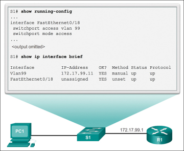
Figure ii-six Verifying the Switch Management Interface Configuration
Source: https://www.ciscopress.com/articles/article.asp?p=2181836&seqNum=4
0 Response to "How To Set Default Gateway On Cisco Switch"
Post a Comment